- Details
- Written by Paulo Administrator Paulo Administrator
- Category: electronicsanddiy electronicsanddiy
- Published: 12 April 2016 12 April 2016
 |
|
How to build an electronic camera slider controller with variable speed and auto-reverse features. |
In my YouTube photography channel, I’ve shown how to build several motorized camera sliders:

These motorized sliders share a common electronic controller design that provides speed control for the gear motor and also an auto-reverse feature using limit switches. In this article , I’ll go over the electronics and software for this slider controller and show how you can build your own.

The Slider Controller
Goals
Before I set out to build this controller, I outlined a set of goals for this project. Here's the original set of design goals:
-
Adjustable Speed: to allow different effects when moving the camera
-
Auto-Reverse: whenever the slider cart hits the end of the slider it automatically reverses direction. This way it can operate indefinitely.
-
Manual Reverse: using a dedicated button
-
Battery Operated: this is important for field operation
-
Portable: Small size is better when carrying equipment in the field
Before we get to the detailed build instructions, let's have a look at the insides of the final product is a shown below with the main blocks highlighted:

Figure 1 - Internal Blocks
For the power source, I opted for two 3.6V rechargeable Lithium Ion batteries in AA form factor so I could use a standard AA battery holder. Owing to the higher power density for Lithium batteries, I was able to power the slider for extended periods of time while keeping the project size small.
A small switch on the side turns that whole setup ON and OFF.
Since the control circuit and the motor run at about 5V DC, I stepped-down the 7.2V source from the Lithium batteries using a small buck converter. I could have used a linear regulator such as a LM317 but the buck (switching) converter is far more efficient and this helps extend the battery life. I’ll have links for these modules which I bought from ebay for about $1.50.
The control board contains a small, 8-pin PIC microcontroller that that generates a PWM signal to the motor. The motor speed is adjusted using a potentiometer and the direction using a small relay. We will look at the circuit in more detail later in this video.
The USB connector shown is used to send the PWM signal towards the motor using two of the four USB wires. The other two wires are used to connect the limit switches in parallel. Note that a third push button resides on the right side of this board and is used to reverse the motor manually.
Links to some of the components used:
- AA Lithium-Ion (3.7V !) rechargeable batteries
Circuit Diagram
Figure 2 shows the schematic diagram for the circuit. Starting from the left, the two LiIon cells connect to the buck converter through the power switch while an LED indicates the power On/OFF state. The buck converter outputs 5V which is used to power both the gear motor and a PIC micro-controller. The micro-controller reads the voltage input set by the potentiometer at GP4 and digitizes it using an internal ADC. Depending on the ADC input value, the internal PWM generator duty cycle is adjusted proportionally. This PWM output at GP1 connects to the gate of an IRF540 power MOSFET that drives the motor supply.
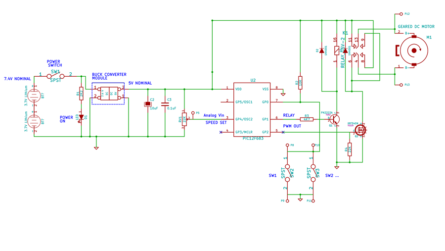
Figure 2 - Schematic Diagram
To automatically reverse the motor direction, the micro-controller continually looks at the GP0 input and toggles the relay state (through transistor T1) whenever one of the switches is pressed. When this happens because a limit switch was hit, then the motor reverses direction as needed. If the manual direction control push-button is pressed, then the motor reverses regardless of where it is positioned. Note that, because the switches are all in parallel, you could add more switches since all the circuit does is monitor the GP0 input and toggle the motor direction when any of them is pressed. Simple, but functional.
The scope plots in Figure 3 show the voltage at the motor terminals with two different speed settings. Notice how the duty cycle changes from one speed to the other. The voltage spikes seen here are the result of the inductive nature of the DC motor used.
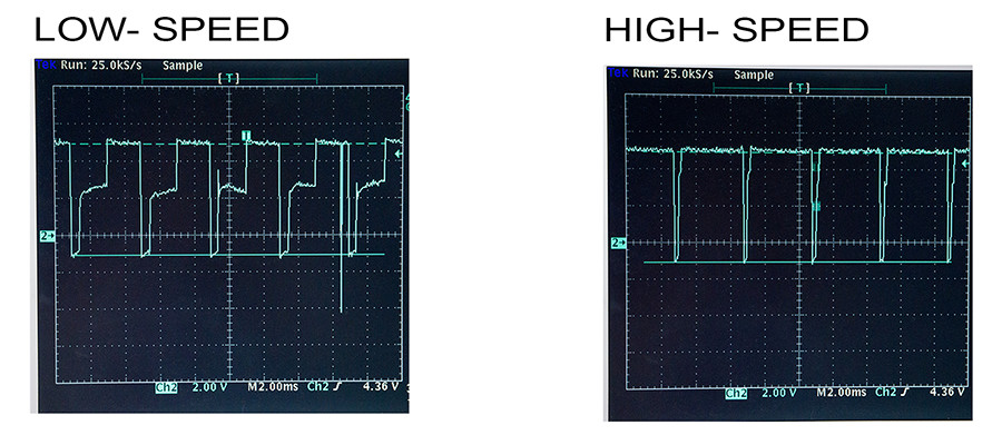
Figure 3 - PWM Duty Cycle Controls Motor Speed
Build Instructions
Figure 4 shows the DC-DC module and one of the AA Lithium cells I used for the project. You will find links to these items in the description.

Figure 4 - DC-DC Converter (Left) and AA Lithium Ion Cell (Right)
You have several options for Limit switches. In this example, I used push-buttons I had salvaged previously from an old circuit board:

Push Buttons Salvaged from another Board
Similarly, any small enclosure box would do but here I decided to re-purpose an old KVM switch box. This has the advantage that there is already a push-button in the box which I used for the manual reverse control. I simply used a Dremmel tool with a cutting wheel to cut this portion of the original PCB.
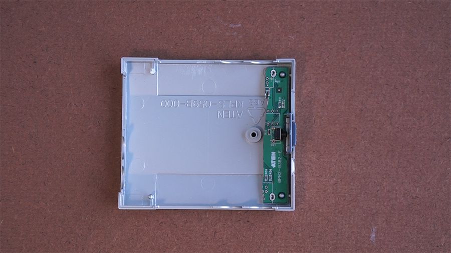
KVM Box with cut PCB
I assembled the control circuit using perf board and wires.
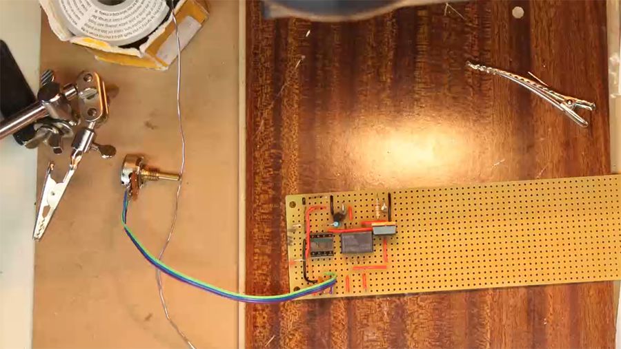
Assembly in Progress
After some soldering work, this is the result:

Notice how the two AA lithium cells fit inside the standard battery holder:

And here’s the final box with the circuit inside. As you can see, this is a rather compact and portable setup which was one of the original design goals.

Final Box Assembly
Let’s look now at how to create the limit switches from the regular push-buttons. As you can see, I used small strips of perf board coupled to a small aluminum L bracket. This makes it easy to both solder the buttons and wiring and also mount the switches on the slider base.

Limit Switches in L bracket
And here you see them in action:

Limit Switches Mounted on Slider
As mentioned earlier, I decided to use USB connectors because the four wires can be reused so that two wires carry the power for the motor and the other two connect to the limit switches. Here I used a female ‘Type B’ connector for the input to the slider, also salvaged from another board. I kept a portion of the original PCB in place since that made it much easier to mount to the base and to solder the wires.

USB 'Type B' connector on Slider Plate
In this example I used a small 6V, 100 rpm gearmotor that can also work at 5V though a bit slower (which is actually an advantage here)

Motor with Plastic Cover
I used a small cup to protect the motor in this build.
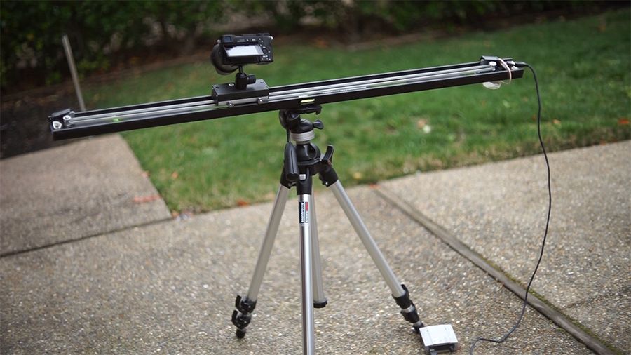
And finally here is the whole setup in action. As you can see this is a very compact system.
Software
The software for the PIC microcontroller was developed in PicBasic Pro and the code can be downloaded here:
If you have a PIC programmer, you can also program it using the .hex file without needing to use the compiler. (And if you are an Arduino user, Google “programming PIC micro-controllers using Arduino” as there are some examples out there though I haven’t personally tried them).
Now having a look at the code, it starts by defining some constants such as the debounce time for the limit switches or the time before it reverses the motor which you can adjust if needed. It then sets some of the ADC parameters on the GP4 input. This is a 10-bit ADC.The PWM is then initialized and set for 10 bit mode so that the resolution is maximized.
In the main body of the program, we enter a main loop which starts by poling the switch input to detect if any of them has been pressed. Note that there’s some debouncing code here. If a switch press is detected, the relay output is toggled.
For the ADC reading, I decided to take 8 samples and discard the edge samples to avoid issues with noise. This is done by sorting the 8 samples and then averaging only the inner samples.
I apply some scaling to the value read by the ADC so that, when the potentiometer is at it’s minimum, the PWM duty is actually a little higher than zero. If you just map the values from the ADC to the PWM you will find that the motor stops towards the low end of the PWM duty cycle. With this scaling transformation, you get a more precise and useful speed control over the range of ADC input values.
Finally, the code returns to the main loop and continues this sequence forever.
Conclusions
So there you have it, this is very versatile controller circuit that I’ve been able to use in all three of the camera slider projects I’ve built recently. I hope you can find it useful for your own projects too.
Youtube Video Link:
Comments, questions, suggestions? You can reach me at: contact (at sign) paulorenato (dot) com
